Each of the Flex 6000 Radios has an I2C port on the accessory which could provide an interface to SmartSDR, but it has not been implemented. Many applications are possible with this kind of interface. PowerSDR was set to output I2C signals over what is called the FlexWire port. In addition other radios like the Elecraft K series offer several bits with band data, these need to drive an RF matrix relay set.
I have supplied many of the I2C FlexWire boards over the past several years, but that supply has run out and I have been giving consideration to the next step. I know that for those who want to do automatic band switching the challenge has always been to find the appropriate RF matrix switch, usually for many more selections than is affordable. Some have been fortunate to find a good deal, but in all cases the next challenge was to handle the voltage level. This is why I always found it convenient to provide an open collector. I always tried to avoid relays to drive relays.
Here is what I have developed as a prototype for the next release of the FlexWire board
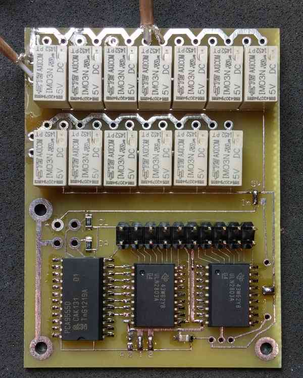
The bottom portion of the board starts out with the original FlexWire circuit. It has the same 20 pin header, but then the output lines of the open collectors go on to directly drive a set of RF relays. There are two matrix sets, one is 6 wide and the second is 7 wide.
So why 6 wide and 7 wide. The 7 wide matrix is to allow for all possible 28MHz IF combinations: 50, 144, 222, 432, 902, 1296 & Intermediate IF. Then the second matrix is for the 144MHz IF radios, up to 6; the Intermediate IF device drives these combinations: 2304, 3456, 5760, 10368, 24192 & 47088. Thus the end goal is rapid band switching for up to 12 VHF/UHF/uW bands.
So how about band switching for the 6000 series of Flex Radios? I have decided to use the FlexAPI to tell me what bands are being used in the radio. I use a BeagleBone Black to subscribe to the radios API Slice information and use that to drive what ever band output is needed. In my shack I use four bits to deliver legacy band data to my existing matrix switches, but I2C is also available on the BBB. My plan is to use the BBB to drive this I2C Dual RF Matrix Relay board.
This board can be used (without the relays) for traditional FlexWire accessories, as well as without the I2C for just a set of RF Matrix Relays
I have made the address lines easier to set, and there is a choice of powering for 12VDC or 5VDC. The RF relays operate off of 5VDC to accomodate TTL levels more easily. You can take I2C and 5VDC right from the BBB and power this directly. Or you can choose to power with +12VDC and the on board regulator will supply the 5VDC for the TTL chips and the relays.
How do these relays perform? On these prototype boards I measured 50db isolation at 28MHz and 45db at 144MHz. The return loss is outstanding, but I have not done final measurements on that yet.
The open collectors are capable of handling 50 volts at 500 mA. The output device is a ULN2803a. Since there are 16 outputs most applications can drive their loads (relays or ttl circuits) without decoding. Reference line is provided to protect from relay back voltage.
Each of the FlexWire interfaces used to come with a short cable to the FlexWire Port. I have substituted a four pin male header so that this cable can be removed. The board has a 20 pin header for all outputs. 5 volts is supplied along with the Reference line that gets connected to the source voltage for relays that are switched by the open collectors. Addressing of the board is flexible, up to 8 of these devices can be slaved (attached) to the FlexWire port. The 20 pin header will also be used for driving the RF relays without I2C. For instance, I envision a daughter board that takes input from Elecraft radios and drives the RF Matrix Relays.
The challenging task will be to wire up the coax and the connectors. I will supply BNC female bulkhead connectors for each RF relay input and output, but do not plan to provide any metal work. I have used both RG316 and RG178. My thinking is that coax can be supplied with the device.
When testing remember that these are open collectors. You will not see any voltage on the outputs, they are NPN and so will conduct to ground when enabled. You can test with modern meters using the diode setting where they provide bias for the test. Or an LED with 1K to the +5 volts on pin 1 will light when enabled. Sample circuit will be provided. If you are not going to use TTL circuits then a relay with positive voltage on one side and the open collector on the other will work. Do not exceed the 500 mA rating.
Output Header Pin outsAccess to the settings for the interface is in PowerSDR for the VHF bands now (as of 2.0). These relate to the bands set up in the XVTR form. To bring up the setup form type Ctrl - Alt - U
Software for the 6000 series will be C compiled code running on the linux environment on the BeagleBone Black. You can supply that or I can supply it preconfigured.
So I know you want to know what the cost will be. I will provide the board wired up as the old FlexWire board was for the same price. The additional cost is the relays. My thinking is to only sell as many relays as are needed. They can always be added. I will likely have a price for a base set of relays and BNC connectors with a per relay/connector add on for additional relays. A fully loaded 13 relay board with connectors and coax will run a little over $100 (~120). How does that compare to a pair of Matrix RF Relays??
Paypal will be used, but at this time I'm looking for interest levels so I can order the appropriate quantities. Please email your thoughts and interest to phil at k3tuf dot com
Thanks, Phil K3TUF